Measuring RF Voltages with a VOM
Page 1 of 1

Measuring RF Voltages with a VOM
![]() projectmaster Mon Mar 02, 2009 7:47 pm
projectmaster Mon Mar 02, 2009 7:47 pm
Simple diode detectors may be constructed to enable ordinary VOMs to measure RF voltages ranging from a few hundred millivolts to the breakdown voltage of the diodes. Figure 1 shows two types of simple detectors, a series detector and a shunt detector. The choice is somewhat arbitrary but the shunt circuit is convenient when using microwave diodes designed to be directly connected to ground. Construction is not critical but the components to the left of the dotted line should have short leads. A termination resistor (such as 50 ohms) may be added across the input for measuring the loaded output voltage of amplifiers and signal sources.
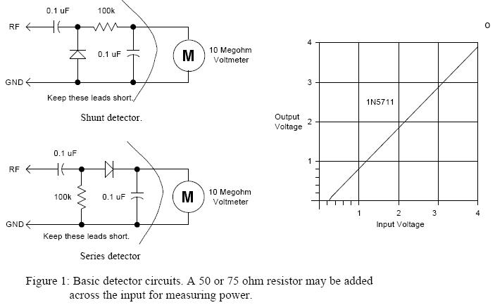
Also try: 1N21, 1N23, 1N830-833, HP diodes: 5082-28xx, 5082-23xx, 5082-29xx. or other point-contact and Schottky small-signal diodes.
A small-signal Schottky diode such as the 1N5711 is probably the most readily available low barrier potential detector but germanium diodes such as the 1N60, 1N34, or even the 1N270 will also give excellent sensitivity. Ordinary silicon diodes such as the 1N914 may be used but the detector will exhibit an offset of about 300mV when measuring peak voltage. The 1N5711 offset is about 100mV and the germanium diodes' offset is about 60mV when measuring RF peak voltage. The voltage probe will read low by this offset when measuring large RF voltages and the probe will begin to exhibit significant error when measuring voltages below about twice this offset number. Fig. 2 shows a simple technique to remove the offset so that the VOM will display the correct reading for voltages above a few hundred millivolts.
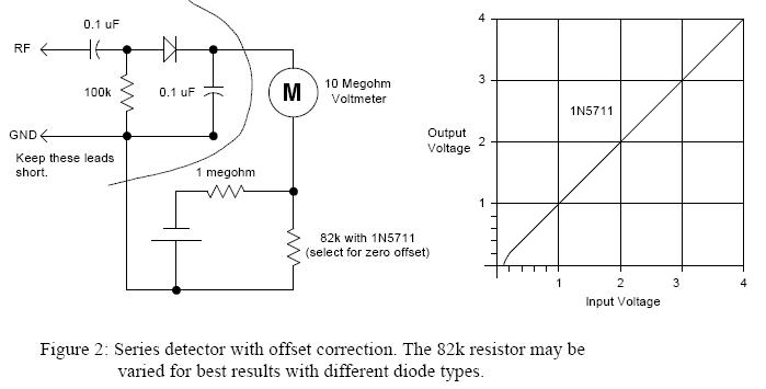
Another diode may be used in place of the 82k resistor for temperature compensation.
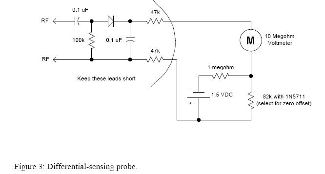
The battery and resistors generate a negative voltage near 100mV which is a good value for the 1N5711. Other diode types may need a different offset correction and the 82k value may be varied to give a correct reading when measuring a several volt RF signal. A 200k potentiometer may be substituted for the 82k resistor if an adjustable offset is desired. If an RMS readout is desired, add a 4.15 megohm resistor in series with the 10 megohm meter. (A 3.9 meg. in series with a 270k will work well.) Fig. 3 shows a differential version suitable for measuring the RF voltage across a component in a circuit. The probe should give the same reading when the leads are reversed.
Diode detectors exhibit a square-law response for input signals below about 100 mV. Power detectors may be constructed taking advantage of this square-law response but their design is beyond the scope of this paper. Several factors must be considered in their design. For best sensitivity, the diode should be matched as closely as possible to the source impedance. Since the diodes usually have a very high dynamic impedance, this matching is usually a "best-effort" with additional lossy circuit elements added to achieve a good VSWR. The diodes are usually biased through a several thousand ohm resistor to lower the dynamic resistance and to extend the square-law response to higher signal levels. The bias resistor may be a thermistor with a negative temp-co. selected to cancel the diode's video resistance temperature coefficient. A second DC-biased diode may be used to generate a temperature-tracking reference voltage to drive a differential amplifier. Another scheme is to add the second diode in the feedback path of a voltage follower as shown below:
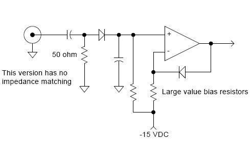
The 50 ohm resistor may be replaced with a 200k ohm resistor to make a high impedance linear-responding probe for signals above about 100mV.
A fifty ohm resistor is included in this circuit since no attempt is made to match the detector diode. The optimum value of this resistance will depend on the diode current and the optimum diode current will depend upon the selected diodes and the matching network, if any. Several parameters must be juggled to obtain the optimum design but the above circuit gives reasonably good performance. The signals are small and the circuit noise will be the limiting factor. Noise at one end and the loss of square-law response at the other end limits the useful range of the square-law detector.
The op-amp circuit shown above works well as a linear detector for signals above 100mV. The resistors may be connected to zero volts, allowing the use of a single power supply voltage. Choose an op-amp with a common-mode input range that includes the negative rail such as the LM358 or LM10 and try 10 megohm resistors and 0.1 uF capacitors.
Also try: 1N21, 1N23, 1N830-833, HP diodes: 5082-28xx, 5082-23xx, 5082-29xx. or other point-contact and Schottky small-signal diodes.
A small-signal Schottky diode such as the 1N5711 is probably the most readily available low barrier potential detector but germanium diodes such as the 1N60, 1N34, or even the 1N270 will also give excellent sensitivity. Ordinary silicon diodes such as the 1N914 may be used but the detector will exhibit an offset of about 300mV when measuring peak voltage. The 1N5711 offset is about 100mV and the germanium diodes' offset is about 60mV when measuring RF peak voltage. The voltage probe will read low by this offset when measuring large RF voltages and the probe will begin to exhibit significant error when measuring voltages below about twice this offset number. Fig. 2 shows a simple technique to remove the offset so that the VOM will display the correct reading for voltages above a few hundred millivolts.
Another diode may be used in place of the 82k resistor for temperature compensation.
The battery and resistors generate a negative voltage near 100mV which is a good value for the 1N5711. Other diode types may need a different offset correction and the 82k value may be varied to give a correct reading when measuring a several volt RF signal. A 200k potentiometer may be substituted for the 82k resistor if an adjustable offset is desired. If an RMS readout is desired, add a 4.15 megohm resistor in series with the 10 megohm meter. (A 3.9 meg. in series with a 270k will work well.) Fig. 3 shows a differential version suitable for measuring the RF voltage across a component in a circuit. The probe should give the same reading when the leads are reversed.
Diode detectors exhibit a square-law response for input signals below about 100 mV. Power detectors may be constructed taking advantage of this square-law response but their design is beyond the scope of this paper. Several factors must be considered in their design. For best sensitivity, the diode should be matched as closely as possible to the source impedance. Since the diodes usually have a very high dynamic impedance, this matching is usually a "best-effort" with additional lossy circuit elements added to achieve a good VSWR. The diodes are usually biased through a several thousand ohm resistor to lower the dynamic resistance and to extend the square-law response to higher signal levels. The bias resistor may be a thermistor with a negative temp-co. selected to cancel the diode's video resistance temperature coefficient. A second DC-biased diode may be used to generate a temperature-tracking reference voltage to drive a differential amplifier. Another scheme is to add the second diode in the feedback path of a voltage follower as shown below:
The 50 ohm resistor may be replaced with a 200k ohm resistor to make a high impedance linear-responding probe for signals above about 100mV.
A fifty ohm resistor is included in this circuit since no attempt is made to match the detector diode. The optimum value of this resistance will depend on the diode current and the optimum diode current will depend upon the selected diodes and the matching network, if any. Several parameters must be juggled to obtain the optimum design but the above circuit gives reasonably good performance. The signals are small and the circuit noise will be the limiting factor. Noise at one end and the loss of square-law response at the other end limits the useful range of the square-law detector.
The op-amp circuit shown above works well as a linear detector for signals above 100mV. The resistors may be connected to zero volts, allowing the use of a single power supply voltage. Choose an op-amp with a common-mode input range that includes the negative rail such as the LM358 or LM10 and try 10 megohm resistors and 0.1 uF capacitors.

projectmaster- Posts : 11
Join date : 2009-03-02
Page 1 of 1
Permissions in this forum:
You cannot reply to topics in this forum|
|
|